Do it yourself experiment: The Enhanced CFR
replication created on September 12, 2005 - JLN
Labs - March 21, 2006 Toutes les
informations et schémas sont publiés gratuitement ( OpenSource
) et sont destinés à un usage personnel et non commercial All informations and
diagrams are published free (OpenSource) and are intended for a private use and a non commercial
use.
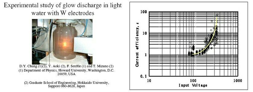
The CFR project is a High
Temperature Plasma Electrolysis fully based on the Tadahiko
Mizuno experiment from the university of Hokkaido in Japan. This
is a very interesting experiment and its implication can be a
real breakthrough in the field of New and Clean energy source....
You will find below an
explanation to replicate yourself the enhanced CFR experiment. With such a design you will be able to
conduct more accurate measurements with better efficiency and
long tests runs.
The enhanced CFR is
composed of a 2000 mL thermostatic reaction vessel filled with
800 mL of demineralized water and Potassium Carbonate ( K2CO3
). The electrolyte solution commonly used is 0.5 molar ( 0.5 M ).
There are three
temperature probes ( K probe or PT100 ). Two probes are used for
measuring the temperature of the cooling water (Temp In and Temp
Out ),
and one probe is used for measuring the temperature of the
electrolyte solution. You need also to use a flowmeter to measure
the cooling water flow.
The Cathode used is a
4 mm tungsten rod. The tungsten rod can be a pure tungsten rod or
a Th-loaded tungsten TIG electrode (WT20) (with thorium oxide ThO2:
1.70% to 2.20% ) commonly used for plasma welding. The use of a
Th-loaded rod increases the life of your cathod. The sputtering
effect produced by the thermionic emission is lower with a Th-loaded rod than with a
pure tungsten rod.
The anode used is
composed of stainless steel mesh ( a grid ) maintained with
stainless steel rods. If
you have planned to conduct some chemical analysis, I recommend
you to use a grid made with platinum or nickel . All the wires
connections are made with a 1.5 mm2
copper flexible wire gained with silicon.
I recommend strongly
to use a high temperature ceramic insulator (ie: alumina) around
the cathod. You may use a common ceramic fuse (ie: a 25A/220V
fuse) maintained by a silicon tube as shown below :
To avoid projections
of some drops of the electrolyte solution from the CFR during the
plasma ignition sequence, I recommend you to put floating balls
on the surface of the liquid (hollow floating balls; pp, 20mm,
2000 PK from Cole Parmer Instrument ).
.
Use a DC Power Supply which is able to give about
300 V DC at 20 A ( don't use AC voltage ). The voltage is tuned with an
autotransformer (see below)
Disclaimer : The
author assumes no liability for any incidental,
consequential or other liability from the use of this
information. All risks and damages, incidental or
otherwise, arising from the use or misuse of the
information contained herein are entirely the
responsibility of the user. Although careful
precaution has been taken in the preparation of this
material. Be Carefull,
you must conduct this test in a
well ventiled room or better in open air,
you must not smoke during the test. This
experiment is not intended for the inexperienced. User
of this document should be very carefull to try
anything out ! If you do it, the risk of any results
is just yours. I take no responsibility of anything
that might happen, let it be of a wrong information
or anything else.
Safety:
BE
CAREFULL, EVERY TIMES don't forget to
disconnect your CFR from the power grid line BEFORE
you touch it...
Conduct your experiment in
a well
ventiled room
or better under a fume hood,
Use protective glasses to
protect your eyes,
Wear a chemistery blouse,
Use high temperature
gloves to protect your hands,
It is recommended to use a
thick (6 mm to 10 mm) sheet of plexiglass between
yourself and the device,
Stay at a least 1 meter
far from the device while it is working,
Use a radiations monitor
(geiger counter) which is able to detect beta, gamma
and X-radiations if you use voltage > 200 VDC,
If your radiations monitor
detects something abnormal, stops immediatly the device,
Don't put too much voltage
( it recommended to use less than 300 V DC ) at the
input of reactor.
Test
procedure :
Switch on the fume hood,
Set the autotransformer to
0 Volt and switch on the power supply,
The voltmeter (set on DC)
is connected at the input of the CFR cell and the DC
current clamp is connected on the positive wire,
Turn the knob of the
autotransformer so as to get 30V DC on the CFR cell,
Let the electrolysis warm
up the cell up to 50°C,
At 50°C drop the voltage
to 0 Volt and switch off the main power supply,
Wait 30 sec to exhaust the
mixture of hydrogen/oxygen,
Measure the temperature ( TSinp ) of the input of the cooling
water,
Measure the temperature ( TSout ) of the output of the cooling
water.
Measure the temperature ( Tr_initial ) of the electrolyte then,
immediatly, switch on the power supply,
Slowly, turn the
autotransformer knob so as to get 200 VDC across the
cell. Start the chronometer,
Note the Voltage and
Current values at the permanent regime (pink glow
discharge),
End the run after ~3
minutes. ( set the voltage to 0 Volt and switch off
the power supply ). Stop the chronometer (time).
Measure the temperature ( Tr_final ) of the electrolyte,
Measure the flow of the
cooling water (Flow in L/min),
Measure the temperature ( TEinp ) of the input of the cooling
water,
Measure the temperature ( TEout ) of the output of the cooling
water.
Melectr = Weight in g of the CFR
electrolyte solution ( K2CO3 at 0.2 M )
Tr_initial = Initial temperature when the
power supply is switched On
Tr_final = Final temperature when the
power supply is switched Off
Flow = Cooling water flow in L/min
TSinp = Cooling water temperature at
the Input just before the start,
TSout = Cooling water temperature at
the Output just before the start,
TEinp = Cooling water temperature at
the Input after the test run,
TEout = Cooling water temperature at
the Output after the test run,
time : Duration of the test run in
sec.
CFR – EFFICIENCY
CALCULATIONS Energy INPUT (
Electrical, DC Voltage )
Important note : With such a design, a COP up to 2 and
more can be obtained. If you conduct yourself the experiment, you
will notice that the value of the COP will increase with the
number of test runs. When the tungsten rod is brand new, the COP
is always less than 1 but becomes greater than 1 when the tip of
the tungsten rod becomes thinner with some small longitudinal cracks visible on it.
I wish you a good
CFR replication experiment and a great COP,
I shall be glad if you could sent me some photos of your working
Cold Fusion Reactor....
For more
informations, please contact Jean-Louis Naudin : JNaudin509@aol.com


 .
.